Products

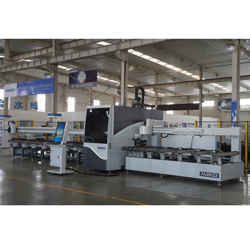

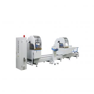
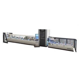
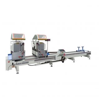
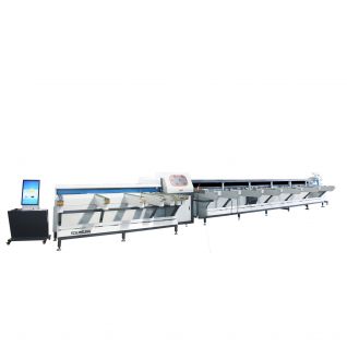
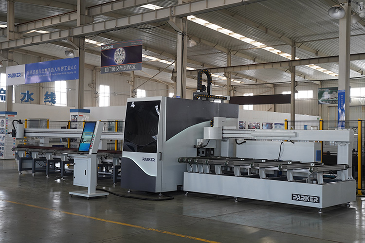
Aluminium-Alloy&PVC Profile Intelligent Cutting Center with CNC A9-S
I. TECHNICAL PARAMETER
Voltage AC 380V 50Hz 3Phase 4Wire
Total Power 15kw
Air Consumption 200L/min
Air Pressure 0.5MPa – 0.8MPa
Weight Around 10t
Overall Size 13000mm×3900mm×3360mm/2500mm(Length x Width x Height)
Blade Diameter Each Φ550(×2)
Blade Spindle Power 3.0kw 50Hz (Single)
Cutting Angle ±45° and 90°
45° Cutting Range 170x130mm(width × height)
90° Cutting Range 170x190mm(width × height)
Cutting Length 230mm(min. size is according to width)~6300mm
Length Precision ±0.1mm
Max. Length 6300mm
Profile Quantity in loading area 6 pieces
Cutting pieces per time 2 pieces
Feeding robot stroke 7360mm
Feeding Robot Speed 40m/min(0.67m/s)
Discharging Robot Stroke 750mm
Discharging Robot Speed 40m/min(0.67m/s)
Blade Vertical Running Speed 0~15m/min(0.25m/s)
II. Machine Features
1、Conveying Section
(1)Function
Robot Arm
a. The X axis is driven by a Schneider motor with a reducer on a flat guide rail through gear and rack meshing. The stroke is 7360mm;
b. The Y-axis and Z-axis are driven by servo and the stroke is 175mm;
c. There are 2 robot arms in total, which can complete synchronous conveying of two materials, and can also convey single-line or double-line synchronously;
d. The foremost pressure pliers of the robot arm can be selected and fixed at any angle through tapping and nut locking, which is convenient for clamping different materials
Lifting Frame
a. The lifting and lowering of the lifting frame is realized by the simultaneous operation of the 4 cylinders underneath. Without ensuring the synchronization of the rise and fall of the 4 cylinders, the auxiliary parts CB are added to each cylinder to buffer them, and when they rise to the highest point and fall to the lowest point, the stroke of the cylinder is in the maximum and minimum limit states.
b. The distribution of the rollers on the lifting frame, the closer to the machine head, the denser the distribution of the rollers, ensuring accurate and stable cutting.
c. The altimeter is installed at the end of the conveying section to detect the height of the processed material, which facilitates the automatic and precise positioning of the saw blade, and improves the processing efficiency and processing quality
2. Machine inside structure
(1)Function
a. The head seat of the saw blade is made of casting parts and 3 process holes are added to facilitate the installation and removal of the electric spindle of the saw blade. The front, back, up and down motions of the saw blade are servo driven by Schneider motor through screw on flat guide rail. Among them, the one-way trip of front and rear movement is 2100mm, the running speed is 15m/min (i.e. 0.25m/s), the running time is 10s, the running speed is 36m/min (i.e. 0.6m/s), the running time is 5s, and the cutting time is 15s for a cycle.The one-way trip of upper and lower motion is 400mm, the running speed is 6m/min (i.e. 0.1m/s), and the running time is 4s.
Note:
**The above-mentioned operating speed and operating time are normal values. Macro-control can be carried out according to the size and processing accuracy of the material;
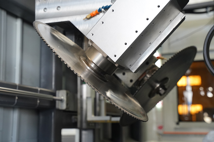
b. Saw blade swing angle(Analyze from the main view)
Saw blade in the front: Push and pull through the cylinder to move up and down on the guide rail. The angle of the saw blade is always fixed at ﹣45°, which is easy to install;
Saw blade in the back: the positioning of the saw blade (45° and 90°) is achieved by pushing and pulling the cylinder with angular contact bearings.
Note:
**When cutting only 90° material, first raise the front saw blade to the highest point, and then push and pull the rear saw blade through the cylinder to achieve 90° positioning of the saw blade; (Pic 1)
** For ±45° cross cutting, first lower the front saw blade to the lowest point, and then push and pull the rear saw blade through the cylinder to achieve a 45° positioning. At this time, the two saw blades are ±45° cross cutting Status; (Pic 2)
⑤The internal conveying and output ports of the machine head have flat pressing and upper pressing, which are all locked by cylinder push and pull
**Each set of clamping devices are equipped with springs for flat compression, to ensure that each discharge can be clamped firmly at one time, and solve the problem of insufficient clamping due to the error of part of the material due to its own width;
**Upward pressing is performed by hand cranking to complete front and back translation;
**The supporting rollers are placed uniformly;
**The flat pressing fixture mounting plate is evenly distributed with openings. Under the condition of ensuring the reliable fixture installation, it can not only achieve the weight reduction effect, but also reduce the accumulation of aluminum chips, which is convenient for aluminum chips to fall into the chip conveyor for centralized cleaning. As shown in the figure below, the inside of the machine head is flat and tight, in non-working state and working state
⑥There is a light strip attached to the decorative panel;
⑦1 camera and 2 lights are installed inside the machine head, which is convenient for the operator to observe the operation and maintenance at any time;
2、Output section
Mechanical structure
①The movement of the clamp in the output section is realized by the cylinder pushing. The total stroke of the cylinder is 750mm, and the running speed is 40m/min (that is, 0.67m/s).
②The clamping method of the clamp in the output section:
When the material is not clamped, the large cylinder is fully contracted, while the small cylinder is fully extended (similar to this state);
When clamping the material, the large cylinder pushes the clamp plate forward, while the small cylinder shrinks, allowing the clamp plate to withdraw, and the material is clamped and taken out through the front and back clamping.
**In order to ensure accurate and firm clamping during the front and back movement of the clamp plate, linear bearings and springs are added to the mechanical structure. The clamping surface of the clamp plate is processed with knurling, which increases friction and facilitates material retrieval;
③Patterns are attached to the outer surface of the synchronous belt of the output section to increase the friction with the material and avoid the material from slipping during the conveying process;